Star Delta Starter Circuit (YΔ) How to Wire + Pros and Cons
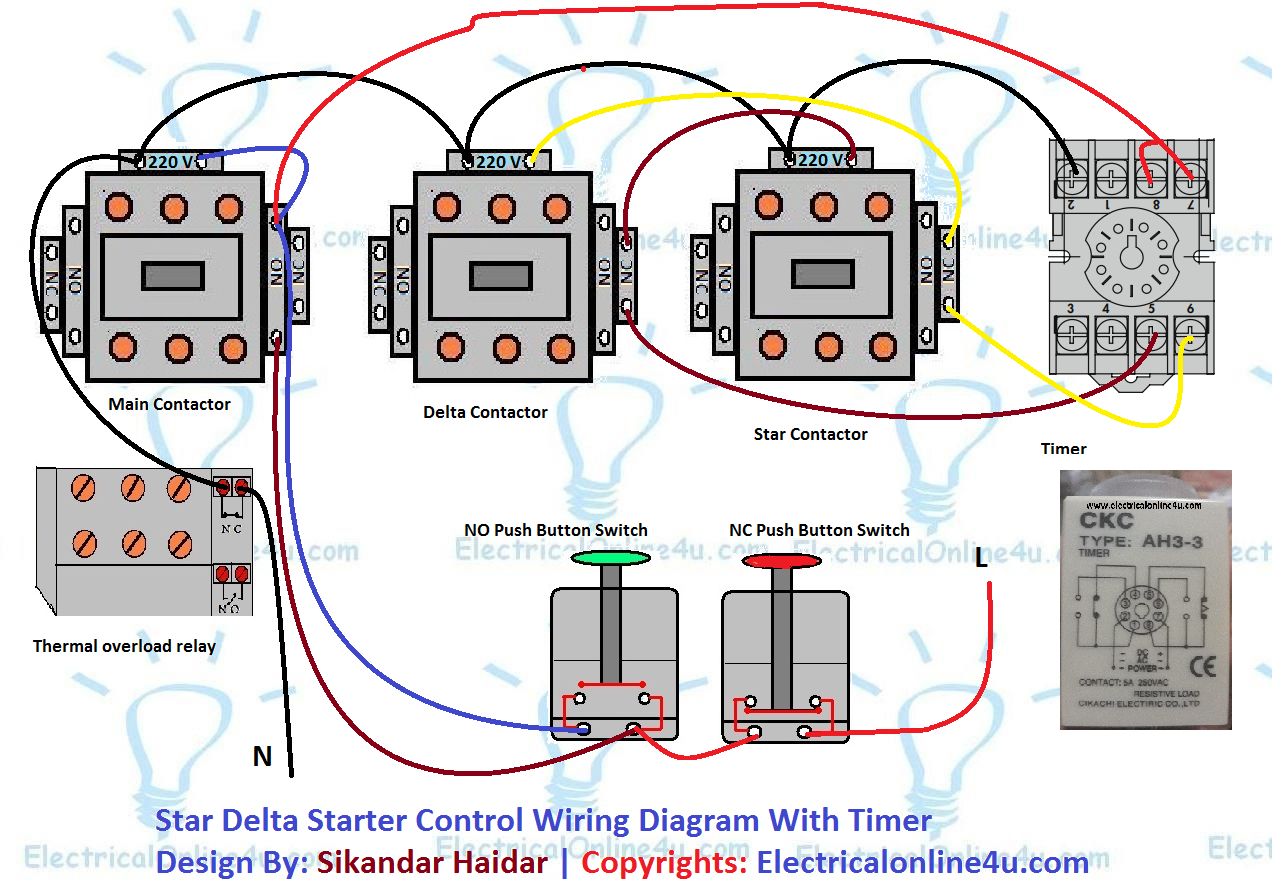
In a PLC-based system, the Star Delta starter using Timer operates in the following manner: Initially, the PLC reads the status of two push buttons, namely "ON" and "OFF". Once the "ON" button is pressed, "Q1" switches on and coil "K1" becomes energized, causing Timer "T1" to Start counting time. Simultaneously, when.

Star Delta Motor Wiring Diagram Wiring Diagram Example
646 25K views 3 years ago Star Delta Starter commonly use in motor to lower the inrush current upon startup of the motor. A Star Delta Starter or Y Delta Connection is the most.
manual star delta starter circuit diagram
For more information on the star-delta starter power circuit and control circuit diagrams, refer to Power Wiring Diagram and Control Wiring Diagram. Star-Delta Assembly Video. To access a demonstration video about the assembly of three contactors for a star-delta application, you can click here, scan the QR code, or copy and paste the link to.
Stardelta starter (WyeDelta Starters) Circuit, working
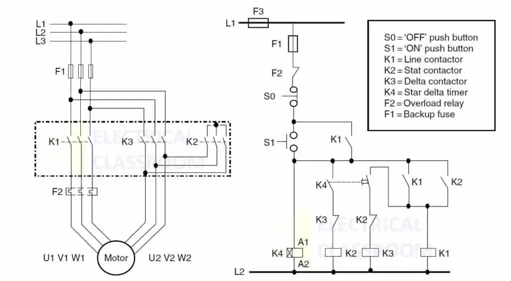
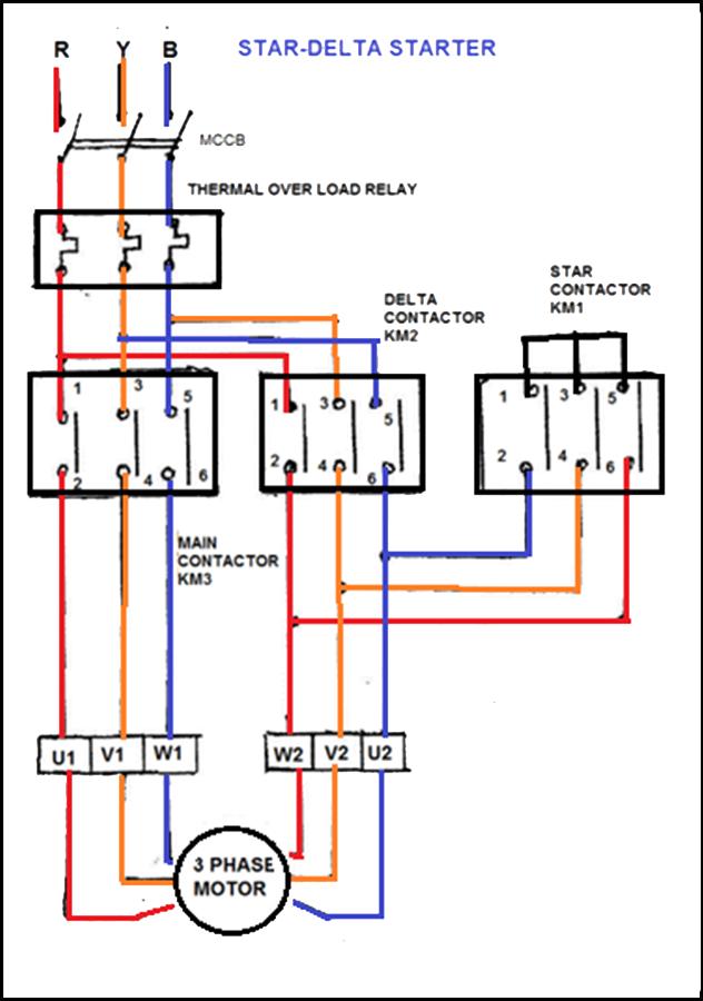
Below are two examples of wiring diagrams for star delta starters from industry suppliers. By the end of this tutorial you will understand how these work. Always check with your manufacturer how, and if, a motor can be connected to a Star Delta starter. Star Delta wiring diagram from Siemens
star delta starter wiring diagram
Star Delta Starters Explained. How do star delta starters work for three phase induction motors and why do we use star delta starters. We cover the basic's o.
Star Delta Wiring Diagram Motor Starter
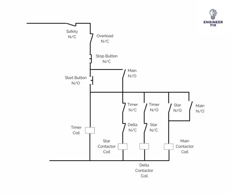
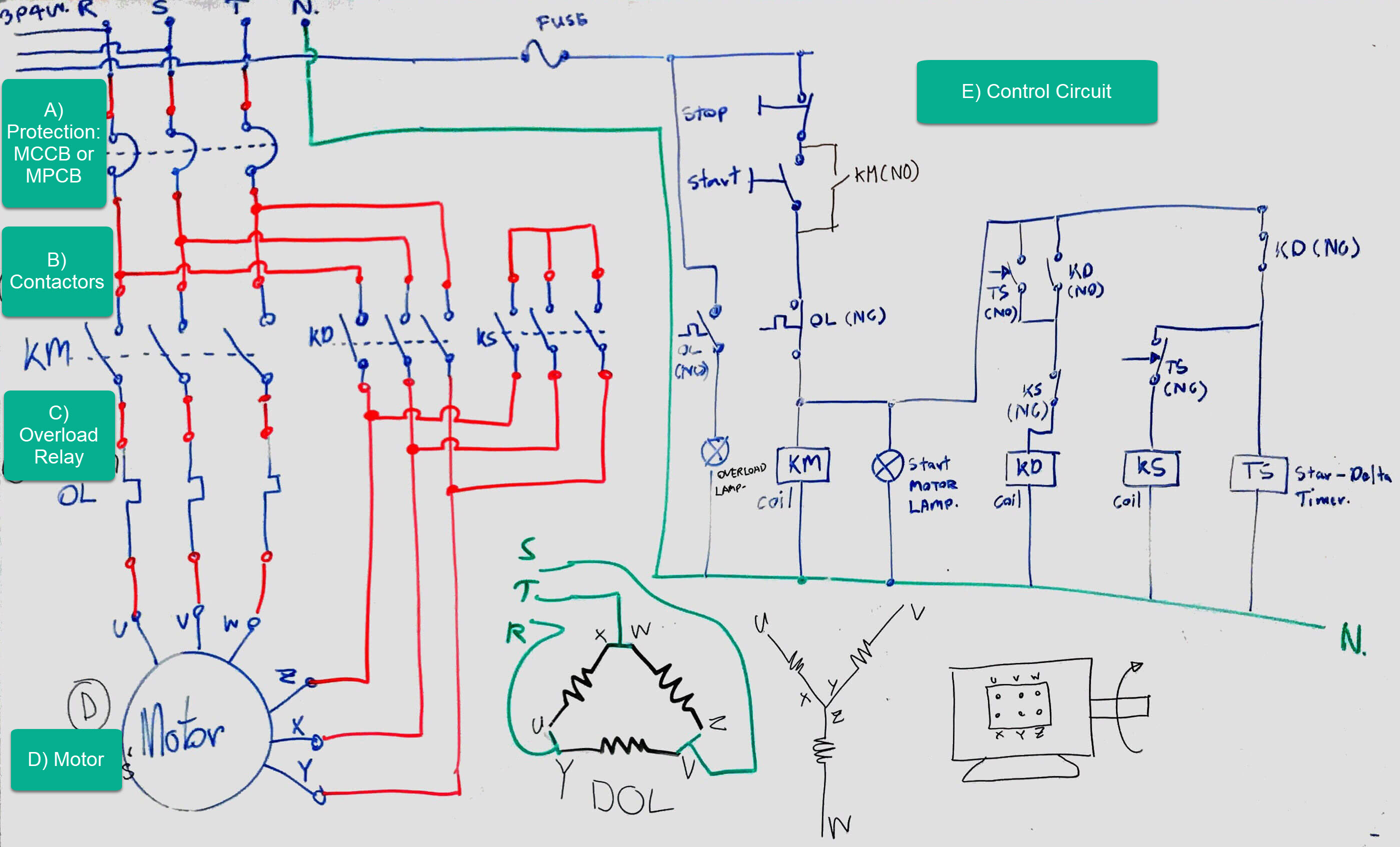
Figure 1 shows the circuit diagram of a typical star delta starter. As mentioned earlier, apart from protection fuses (F1), and overload relay (F2), the circuit consists of three contactors - a line or main contactor (K1), a delta connection contactor (K2), and a star connection contactor (K3).
What is Star Delta Starter? Working & Diagram ElectricalWorkbook
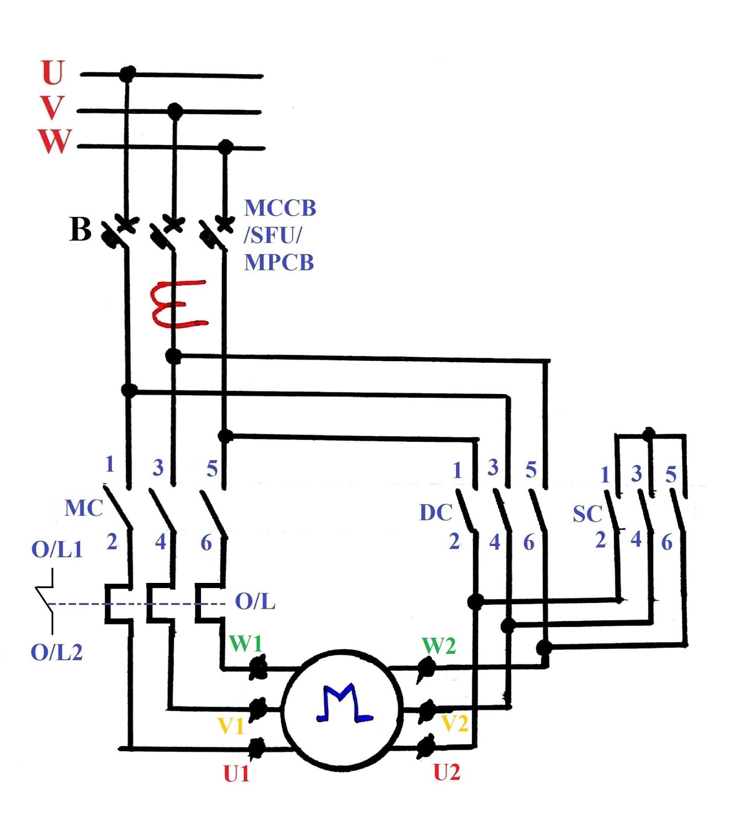
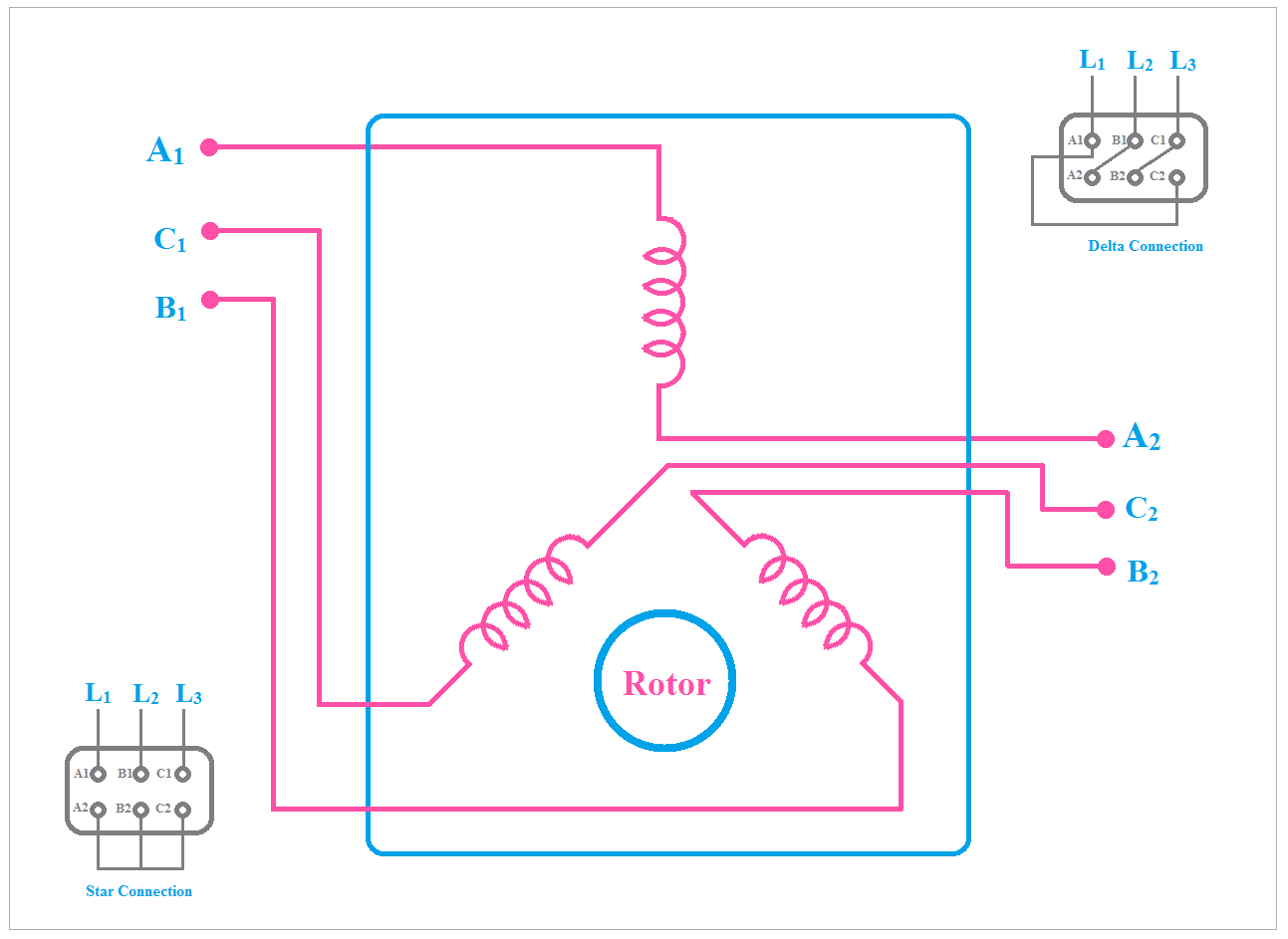
Star Delta Starter Circuit Diagram The motor terminal connection in the case of star and delta is shown in the above figure where U1 V1 W1 is the start terminal of each winding and U2 V2 W2 is the finish of each winding. L1, L2, and L3 are the three-phase line connecting terminals.
Wiring Diagram Star Delta Starter
This wiring diagram is designed to reduce the amount of current flowing through the system by providing a separate path for the three-phase current. By using the star delta circuit, a technician can easily control the starting and stopping of the motor, as well as the speed at which it runs.
Wiring DOL Starter Motor (Star Delta). Electrical Engineering Blog
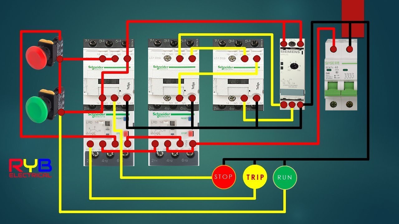
Star delta starter - Power diagram The image above shows how to wire the power circuit of a star delta starter. The power circuit shown above uses three phase power and passes through a number of electrical components.
Star Delta Starter Reverse Forward Control Without Timer
star delta starter control circuit wiring diagram In this video, we'll show you how to do control wiring of a star delta starter, this type of starter i.
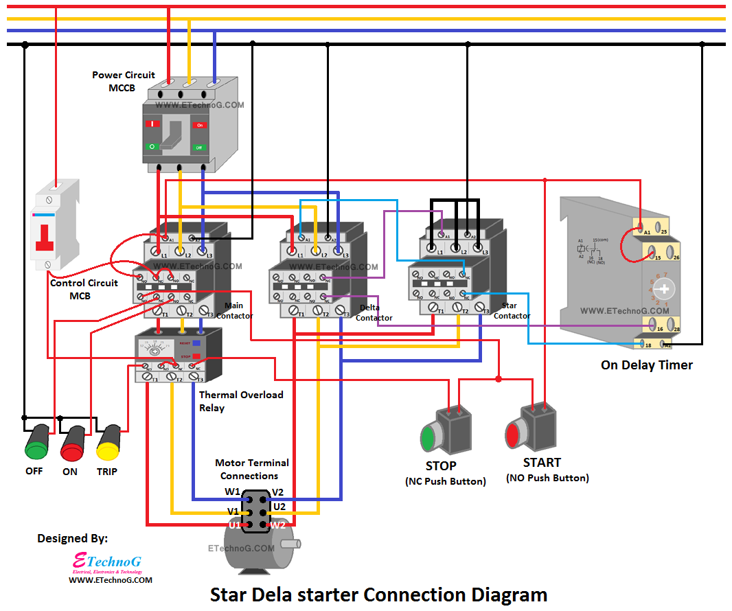
[Explained] Star Delta Starter Diagram Control and Power Circuit ETechnoG
1. OFF Stat ⇒ This is the off stat of the starter, all the contactors are in the OFF position. 2. STAR Stat ⇒ In this stat, Main and Star contactors are closed and Delta contactor is open. The motor is connected to STAR. 3. OPEN Stat ⇒ This stat is the transition stat from STAR to DELTA.
The Beginner's Guide to Wiring a StarDelta Circuit Factomart Singapore
2. Fully Automatic Star Delta Starter: 2.1 Product description 2.2 Wiring diagram 2.3 Technical Details 2.4 Installation 2.5 Operating procedure in normal condition 2.6 Troubleshooting guidelines in case any incoming fault is present before switching ON the motor 2.7 Troubleshooting guidelines in fault condition when

Star Delta Starter (YΔ) Starter Power, Control & Wiring Diagram Electrical circuit diagram
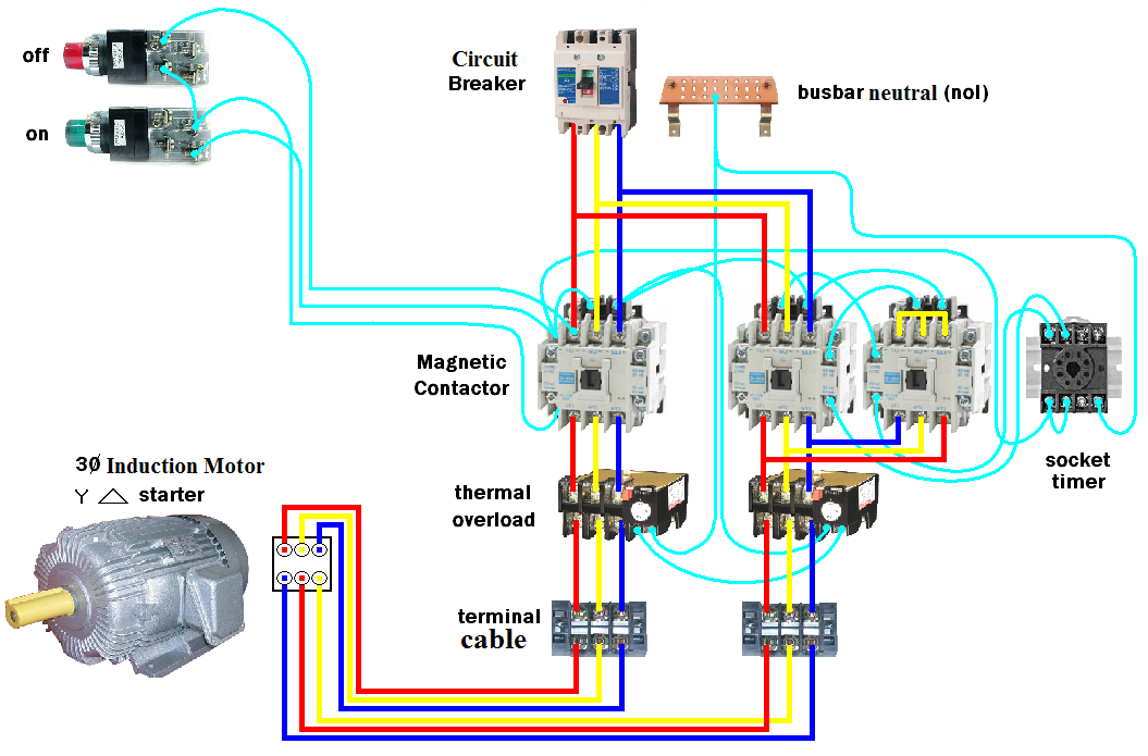
Each starter is delivered assembled, bare, cabled by us and contains: 1 KM1 "line" contactor, 1 KM2 "star" contactor, 1 KM3 "delta" contactor, the hold-in contacts, 1 "star" and "delta" contactor mechanical and electrical interlock device, the space for the thermal O/L relay (direct mounting). The thermal O/L relay must be supplied separately.
Wiring Diagram Of Star Delta Motor Wiring23
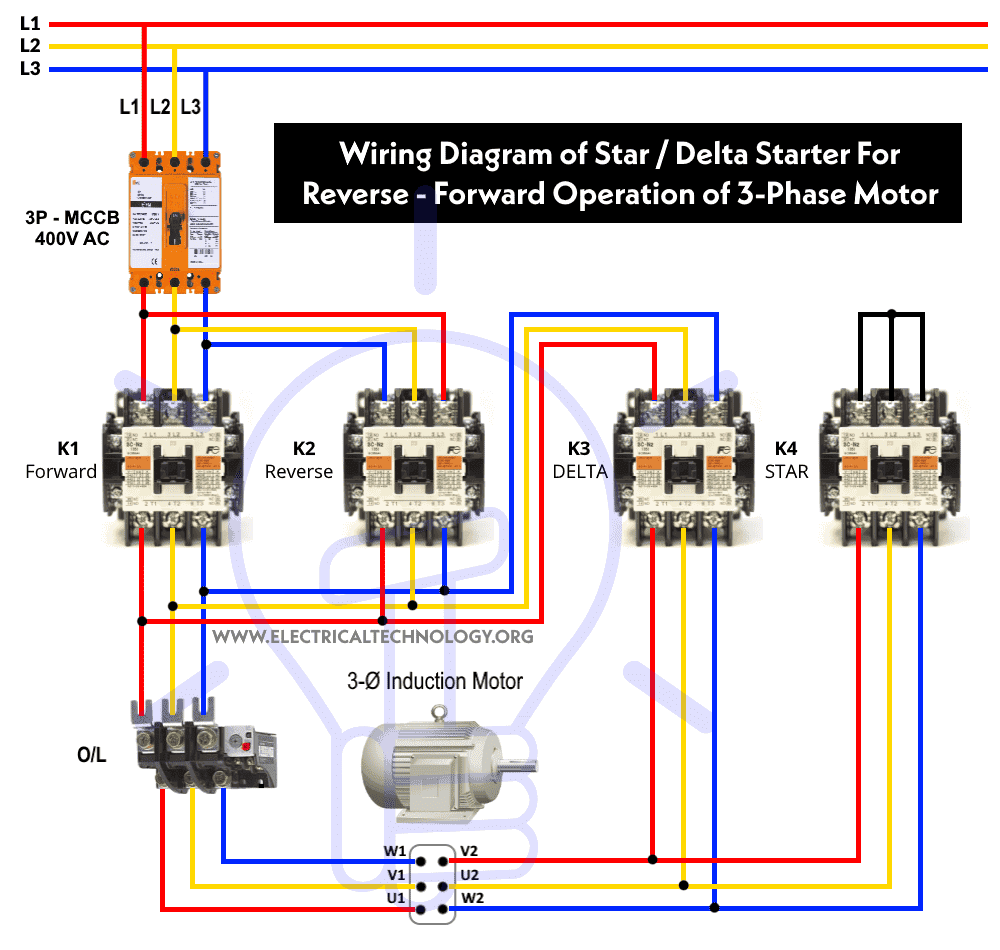
Automatic STAR/DELTA Starter Using Timer - Power, Control & Wiring Diagrams Reverse/Forward 3-Phase Motors using Start-Delta Starter & Timer - Power & Control Diagrams REV-FWD Three Phase Motor using Star/Delta Starter without Timer Introduction to Star-Delta Starter
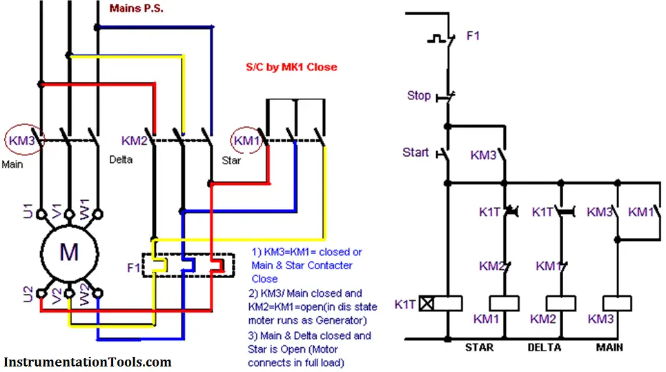
Motor STAR DELTA Starter Working principle InstrumentationTools
The Star/Delta (or Wye/Delta) starter is one of the lowest cost electromechanical reduced voltage starters that can be applied. The Star/Delta starter is manufactured from three contactors, a timer and a thermal overload.
Circuit Diagram Of Star Delta Starter
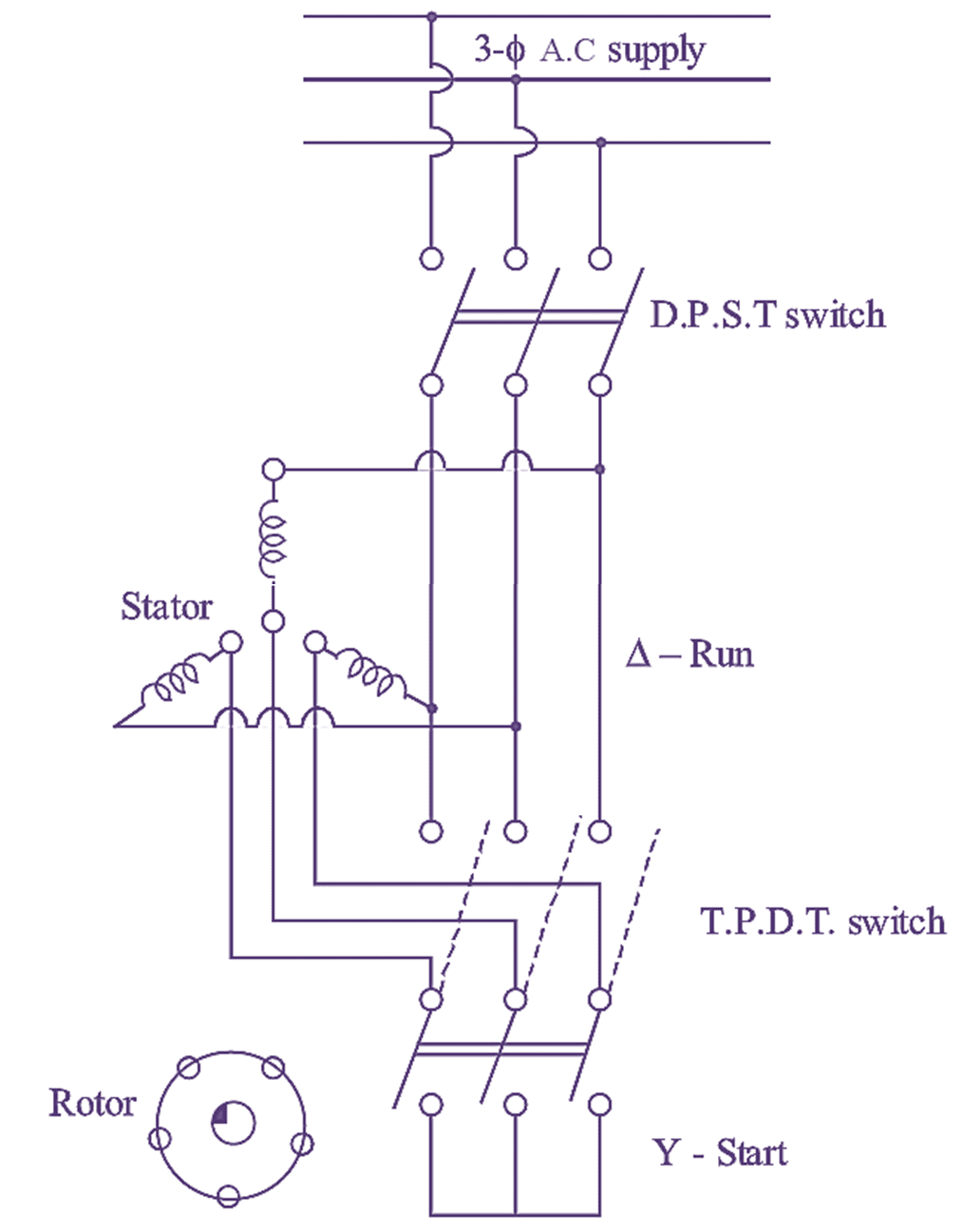
In star delta starting an induction motor is connected in through a star connection throughout the starting period. Then once the motor reaches the required speed, the motor is connected through a delta connection. A star delta starter will start a motor with a star-connected stator winding.